


0.00

|
|
 |
|
A central vacuum system can be installed in both new and existing homes without any difficult labor. This guide will outline the necessary steps and procedures that should be taken to successfully install a central vacuum system in both an existing home and a new home being built. Before beginning any installation, it is important to plan each step carefully and consider all cleaning situations to properly plan how many inlets you will need in order to effectively clean the entire surface area of your home. Proper ventilation methods and building codes should also be taken into consideration before beginning your installation.
The first step to any central vacuum installation is to gather all of the necessary tools.
The tools needed are as follows:
|
|
|
|
|
|
|
|
|
|
|
|
|
|
|
|
|
|
|
|
|
|
|
|
|
|
Helpful Hints:
- A tubing cutter will ensure cleaner cuts.
- Use 14" cable ties rather than 11" ties to make sure that the ties will fit around the pipe.
- If you do not own a right-angle drill, rent one for use.
Location of the Power Unit
If possible, the power unit should be placed in a heated area like the utility room, garage, laundry or storage room. If the power unit is installed in a cold storage room, the vacuum tubing and the exhaust pipe should be insulated in order to avoid condensation. In buildings with two or more stories, always place the power unit on the lowest floor. If the unit is placed on the upper floor, the vacuum must be more powerful so that even the heaviest dust particles can be suctioned and transferred into the dirt receptacle. When selecting the mounting location, it is recommended that you ensure that placement does not disturb your neighbors or interfere with your own comfort and activities. Make sure that there is an electrical outlet nearby to power the unit and ample space for the system to ventilate while circulating air on all sides of the unit.
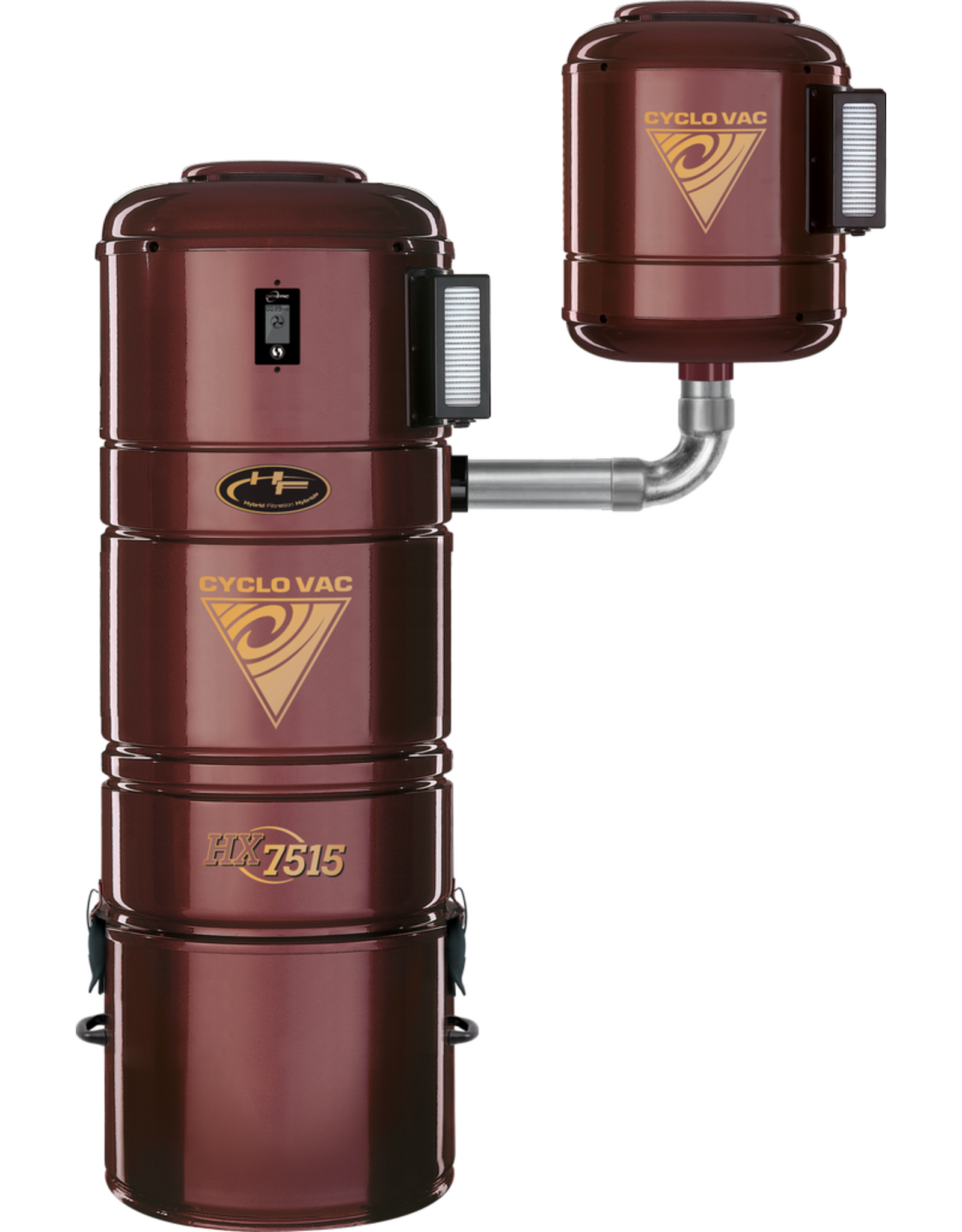
There are several types of central vacuum power units. These include filtered paper bag systems, cyclonic action systems which use drop down filters, cartridges or washable filters and true cyclonic separation systems. When using a true cyclonic unit, you must always vent the unit outdoors. All units can be mounted outdoors to increase filtration efficiency and rid the home of unwanted allergens and dust.
Tubing System Design
The most important principle for designing the layout of the tubing system is to keep it as short as possible. This will give the highest possible vacuum performance. However, the main tube can be routed in different ways. The outside diameter of the tubing system is 2" and is 2-1/8" at the extension. The through-holes in the walls must be 2-3/16" to 2-1/2" in diameter so that the extension and the low-voltage cable can also go through the opening. The minimum diameter of the exhaust tube is 2-1/8".
Before installing tubing to carry dust and dirt from the inlets to the power unit, plan your route. Running the tubing beneath the sub-floor whenever possible makes tubing easier to work with and creates the shortest path between the inlet valves and the power unit. If the tubing must run next to a water heater or chimney flue—for your safety and to comply with building codes—use metal central vacuum system tubing for that section. If the tubing runs through an unheated, cold or other unprotected environment, wrap it with insulation to prevent condensation and the possibility of clogging.
In new one-story houses, the horizontal main tube is placed in the under-house crawl space or in the attic. In the under-house crawl space, the tubing should be insulated. Tubes to the inlet valves are routed in the partition walls or between secondary spaces, such as closets. In a cold attic, the tubes should be covered with insulation in order to avoid condensation. In two or multi-story houses, the main tube is placed in the under-house crawl space, attic, closet, or between walls. Existing homes can be a little different. The main tube can be installed on the surface in existing secondary spaces, such as a garage or storage room.
The tube can also be routed through the attic and then vertically inside the partition walls and closets all the way to the inlet valves. A lowered ceiling and closet footings can also be used for routing of the tubes.
Location of Wall Inlet Valves
Central locations like hallways or closet walls and/or doorways make great locations for central vacuum inlet valves. Make sure to place the inlet valve accordingly so that you may reach every corner of the room with a hose that is 25 to 35 feet long. When you've chosen a possible location for an inlet valve, use a piece of string that is cut to be 35 feet long and tape it or have someone hold it at the area where the inlet will be installed. Walk around the room with the piece of string making sure that it reaches every corner to ensure that you will be able to clean the entire room with a 30-35 foot hose. If you cannot reach every corner with a 35 foot piece of string, you may need to install additional inlets.
When a possible placement area for an inlet valve has been found, use a stud-finder or sound-out the wall to make sure the site for the valve is between the studs and that the space is open behind the wall board. Also check the other side of the wall to make sure it's clear of obstructions such as utilities and outlets. Do not install an inlet behind a door or in a wall that has a pocket door.
Mark the installation points of the inlet valves in the layout drawings using wire of the same length as the actual vacuum hose. When using drawings scaled 1:1000 the wire length is 3-1/4", and when using drawings scales 1:50 the wire length is 6-1/2". The most suitable places for inlet valves are entrance halls and hallways.
Typical Installation Examples
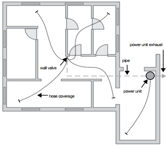
In a typical hose only two inlet valves are needed. In such cases, the utility valve of the power unit can be used for cleaning the basement because it often covers the whole basement area.
In the house of the same size, the power unit is in the garage, where the utility valve serves as a third inlet valve allowing you to clean your car, for example.
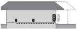
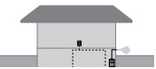
In this example, the main tube has been routed under the hose. However, the tube in the under-house crawl space should be insulated to avoid condensation.
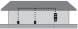
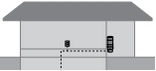
In this example, the simplest solution is to route the tubing in the attic. If the space is cold, the main tube should be insulated.
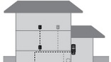
The whole floor area can often be vacuumed from one single inlet valve. The light, broken line indicates an alternative installation type where the unit is mounted in the basement.
It is recommended to place the inlet valves in between different levels. In such cases, you can easily clean tow levels from one inlet valve. The power unit is placed in the storage room.
Installation of the Wall Inlet Valves
A typical wall inlet valve installation is shown in the figure on the right. A 90 degree inlet elbow is used in the wall installation to prevent long objects from entering into the system, protecting it against blockages. A 90 degree steep elbow can be fitted in two different ways. In practice, the partition wall can be as narrow as 2-3/4". Note: A 90 degree inlet elbow must not be installed anywhere in the tubing system other than at the inlet.
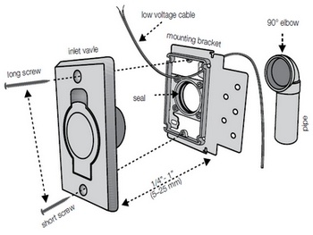
If the thickness of the wall board is more than 1", you can reach the mounting bracket by using an extension tube.
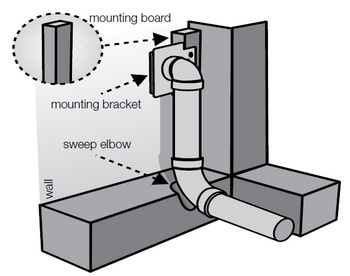
If the structures of the house prevent tubing routing, make slots like the ones shown in the figure to the right. Supporting structural elements of the house should not be slotted. If you cannot attach the mounting bracket properly to the batten wall, you can install a separate mounting board.
Directly below the proposed site of the inlet valve, wedge the molding aside using a flat-bladed screwdriver. Then, take a wire coat hanger and snip a long straight piece from it. Insert the wire into the chuck of your drill and then holding the drill vertically beneath the intended site, slowly drill down into the floor alongside the baseboard or where the wall and floor intersect. Release the wire from the drill chuck and leave it in the pilot hole to serve as a locator. Then go to the basement and locate the wire protruding from the ceiling.
Now you will be able to see where the inlet valve will be above you. Measure from the wire to find the center of the sole plate and wall cavity. At this time, you may want to drill a 3/4" diameter inspection hole to avoid cutting into the bottom of a stud or other inner-wall obstructions. Then, using a flashlight or probe, inspect the interior of the wall to be sure there are no obstructions. If there are any obstructions, you may have to move the site of the valve. If there are no obstructions, drill a 2-3/8" diameter hole in the bottom of the hollow wall through the sole plate. Make sure to cut in between the walls. Vacuum tubing is 2" in diameter, so the hole will give you room to manipulate the tubing and low voltage wire. If you are using PVC schedule 40 pipe, drill a 2-5/8" diameter hole. Again, check for obstructions using a flashlight and a length of tubing. If there are no obstructions, go back upstairs and mark the inlet location on the wall. To do so, at the electrical outlet adjacent to the inlet site, measure up from the floor to the center of the outlet. At the proposed inlet site measure up from the floor the same distance. This will be the center of your inlet valve. If you prefer, you may locate the inlet at a more convenient height.
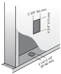
To install the inlet valve, make a hole in the board material between 2-1/4" and 2-1/2" in diameter. The size of the rectangular opening should be 2-3/8" x 4-3/4". In existing houses where tubes are routed underneath, a hole can be drilled for the tube using a guide hole as a template. Glue the 90 degree inlet elbow onto the sleeve of the mounting bracket. Leave a gap of approximately 5/8" for the low-voltage cable to be connected to the inlet valve. Then glue the dust tube into the inlet elbow.
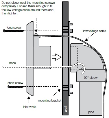
Strip off approximately 1" of the insulation from the end of the low-voltage cable. Roll the end of the cable two turns around the screws in the inlet valve and tighten the screws. Screw the inlet valve into the mounting bracket and make sure that the screw does not extend through the tube. If necessary, use shorter screws. In a complete wall structure, the mounting bracket is held in place by a hook as shown in the figure.
Another method of installing an inlet valve is to take your wall mounting bracket, cut or snap off the new construction flange and dispose of it. Use a level to make sure the mounting bracket is level. Then trace the outline of the mounting bracket onto the wall. The top and bottom cuts are critical since the flange will rest on these areas. Take a utility knife and score the lines. Then use the utility knife or a drywall saw to cut a hole through the drywall. This will be much easier if you use a drywall saw.
Attach a short 90 degree elbow to the flange on the back of the mounting bracket. Apply glue around the outside of the mounting bracket flange and twist the short 90 degree elbow into place. Make sure the open end faces the direction it will meet the tubing—usually straight down. Never apply glue to the inside of fittings or tubing. Apply glue only to the outside of the tubing. This will prevent glue from creating obstructions which could clog your system. Run about 6 inches of low-voltage wire through the guide hole in the mounting bracket. Split the wire into two strands and strip one inch of insulation from each strand. Wrap the strands in a clockwise direction around the screws on the back of the inlet valve. Then, tighten each screw.
Next, attach a weight to the end of the low-voltage wire and drop it down to the basement or crawlspace. Have a length of wire coat hanger ready with one end bent into a hook. Insert the mounting bracket in place. Then, slide the inlet valve face plate along the wire hanger into the mounting bracket. Screw the valve into place. Remove the wire hook. Be sure to mount the inlet valve face plate so the lid pulls down to open. Then apply glue to an adequate length of tubing and aim it upward through the hole in the sole plate and into the short 90 degree elbow on the back of the mounting bracket.
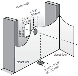
If you cannot locate a hollow wall, or the space between your walls isn't wide enough, there are two alternatives: one is to run the tubing through a concealed area, such as the inside of a closet, then run the tubing downward. When running tubing through a closet wall, choose a location and make a 2-1/8" x 2-3/4" diameter hole is needed. Drill a hole for the tube also in the floor of the closet. Cut the tube to the proper length and glue it into the rebuilding sleeve.
Insert the tube into the round hole with the floor sleeve/rebuilding sleeve first so that it extends through the outer wall of the closet. Mount the inlet valve in the rebuilding sleeve. Measure and cut the tube to the proper length so that it reaches with the inlet elbow to the vertical tube.
Tubing System Installation
Begin the main tube installation with the farthest inlet valve and place the tubes temporarily at first. Do not glue the joints yet until you have made sure that the tubing routing is correct. The glue will dry quickly; therefore, the joints have to be fitted right after applying the glue. When measuring the tubes, take into account that the tube goes approximately 2/3" into the sleeve and approximately 7/8" into the extension tube. The tubing system can also be installed in a floor that will be concrete casted later—shown in the figure to the right. In such cases, the low-voltage cable must be protected by a conduit pipe. The conduit pipe should be attached to the vacuum tube or the casting net. For the vacuum tube, the routing channel has to be 2" wid. The ends of the vacuum tubes and the conduit pipes should be plugged before the concrete casting.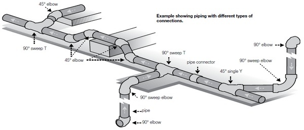
Important notes for installation:
1. The 90 degree inlet elbow may be installed only together with the mounting bracket and the inlet valve. Anywhere else in the tubing system, 90 degree sweep elbows and 45 degree elbows should be used.
2. Tubes are cut straight so that the cutting line is not slanted. Use a miter saw if possible. Cut edges can be finished with a knife.
3. For tubing joints, use suitable PVC glue to make the fittings secure and tight. Apply a thin and even layer of glue only to the end of the tube - not to the sleeve. This will prevent glue from overflowing to the end face of the tubing. Close the glue can carefully immediately after use and make sure to have adequate ventilation during installation. Avoid inhaling glue vapors. Insert the tube all the way into the sleeve while turning it at the same time..
4. The inlet is made through the fire wall or by using a 2" diameter fire cuff. Check the inlet with your local fire codes.
How to Minimize Condensation
If the tubing installation is carried out in winter, a large amount of condensation may be generated. To reduce the amount of condensation, close all pipe holes and inlet openings using duct tape during installation. Before starting to use the central vacuum system for the first time, let the system vacuum and circulate fresh air for a few minutes, and make sure that there is no water in the dust container. If there is water in the container, drain it and continue vacuuming until no more water is accumulated.
Specialty Inlet Installations
Owning and operating a central vacuum system in your home has many advantages. This is especially true because of the thousands of different specialty inlets that can be installed in your home. These include popular items like the VacPan and DrawerVac as well as the Hide-A-Hose, Wally-Flex and even the standard utility valve that can be used to clean the car in the garage. This next part of the installation guide will describe how to install all of these different specialty inlets.
How to Install a VacPan
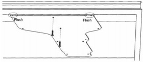
VacPan systems are very popular in kitchens, bathrooms and even hallways. In fact, in some homes with all hard flooring, only VacPans are used. To properly use this type of inlet, sweep the floors as normal and kick open the VacPan to operate the suction while sweeping dirt and debris into the vacuum. To install your VacPan, first determine the best place to install the dustpan; either under a cabinet or in the wall. Keep in mind that the leading edge of the VacPan must sit flush with the finished floor. Plan the location of your dust pan to be conveniently located for sweeping clean-ups. Also consider ease of access of vacuum tube piping connections during installation.
For maximum clearance, use a short 90 degree elbow for connection at the inlet. Do not glue the connection between the VacPan and elbow. Teflon tape may be used if required. Allow for 1/2" vertical play in vacuum tube piping at the dust pan's location, so that final piping connections can be made. Two inch wire re-inforced flex pipe may also be used.
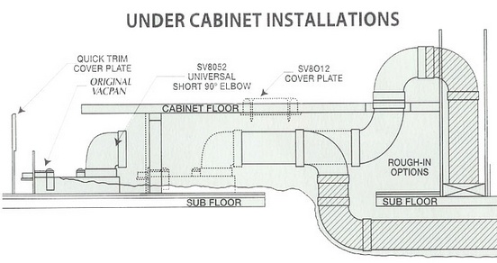
For installations underneath a cabinet, the VacPan requires a minimum toe kick height of 3-1/2 inches. Once the location has been determined, cut a 6-3/4" long x 1-3/4" high slot in the cabinet toe kick to accept the inlet. Run vacuum tube piping and low voltage wire from the main piping to the inlet location. Access for final piping connections must be made.
If access is available from below, cut an access hole through the subfloor underneath the cabinet, positioned so that final piping connections can be made by reaching through the access hole. Access can be made through the finished cabinet floor. Cut a 2-3/4" x 3-1/2" access hole, positioned so that final piping connections can be made by reaching through the access hole. A cover plate can be used to cover the hole after installation. Access can be made through the cabinet toe kick by cutting up to a 10-1/2" x 3-3/4" slot and using the Quick Trim Cover Plate. If required, score the back of the cover plate with a knife and snap it along the grooves for height adjustment.
Attach low voltage wires to the VacPan terminal connections marked "low voltage only". Slide the VacPan into the mounting slot and secure it to the toe kick using the two screws provided.
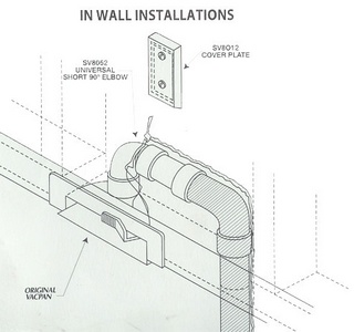
To install a VacPan in an existing wall, locate the area between the studs. The inlet should be installed tight to one side in stud space. Once the location has been determined, cut a 6-3/4" long x 1-3/4" high slot in the wall and baseboard to accept the VacPan. The 2x4 wall bottom plate between the two studs must be removed. This can be achieved from below by using a hole saw. In new home construction, the bottom wall plate can be removed directly. A 6-3/4" length of 2x4 can be used as a temporary rough-in block, that will force all trades to finish around, leaving a slot for the inlet. Floor contractor must run flooring under this block.
Run vacum tube piping and low voltage wire from the main line to the inlet's location and make access for final piping connections. If access is available from below, cut an access hole through the subfloor underneath the wall between the studs, positioned so that final piping connections can be made by reaching through the access hole. Access can be made through the finished wall as well. Cut a 2-3/4" x 2-1/2" access hole, positioned so that final piping connections can be made by reaching through the access hole. A cover plate can then be used to cover this hole after completion of installation.
Attach the low voltage wires to the VacPan terminal connections marked "low voltage only" and slide the inlet into it's mounting slot, securing it to the wall with the screws provided. Reach through the access hole and make the final fitting connections.
Installing a DrawerVac
DrawerVac can be installed in any cabinet configuration with minimum inside dimensions of 12" wide and 22-5/8" deep. This guide will provide simple installation instructions for a drawer-activated inlet in your central vacuum system.
The first step is to confirm that the cabinet has the following minimum inside dimensions: Width of 12" and depth of 22-5/8". DrawerVac requires a level mounting surface for installation. It may be necessary to level the undercounter surface using plywood or other sheeting material. If you are installing the inlet in a drawer application, trimming the back of the drawer may be necessary to create the required clearance for DrawerVac to fit.
Begin by mounting the cover to the under-counter surface using the 2 interior screw holes as shown to the left. Be sure the front edge of the cover is flush with the cabinet face. Warning: Be sure not to drill or screw through the top of the counter.
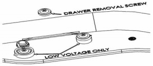
Install the DrawerVac assembly using the remaining 8 screws, with the tray inserted in the shell. Connect the central vacuum piping to the inlet using either solid or flexible central vacuum piping. Connect the low voltage wire with the 2 screws shown on the right to complete your installation.
Installing the Power Unit
Attach the power unit to the wall withing six feet of a grounded electrical outlet ensuring it will be easily accessible for emptying the dirt receptacle, at least 18" from the floor. For proper motor cooling, there must be at least 12" between the unit and the ceiling. Do not install the power unit where the ambient temperature regularly exceeds 120 degrees Fahrenheit.
If mounting on plaster, wall board or panel walls, be sure mounting bolts enter studs. If mounting on a block or concrete wall, drill the holes with a masonry bit and insert plastic or lead anchors. As an alternative to mounting on concrete walls, suspend 2"x4" studs or plywood from overhead.
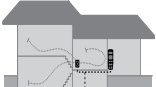
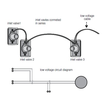 To power the central vacuum system, a 24V low-voltage cable is routed to each inlet valve. Parallel connection is made according to the figure to the left. It is recommended that low-voltage cable be installed in a conduit pipe and this is absolutely necessary when cables are to be hidden in cast concrete. If the cable becomes defective, it is also much easier to change it afterwards. In these installations, only certified electrical components may be used.
To attach the low-voltage wires, strip the wire and crimp the strands into the two spade terminals provided. Attach the terminals and plug the power unit into the dedicated electrical outlet. If an outlet is not located within 6 feet of the power unit's location, an electrician can carry out the installation. Once plugged in, the sentry light should come on. Turn on the switch, if applicable, and the power unit should turn on. Attach the remaining section of tubing to the power unit with connectors and clamps. Do not glue this connection because you may need to disconnect the system at a future date. For added installation convenience, some power units may have inlet connections on either side. If your system uses a muffler, clamp it to the exhaust port.
Please note that true cyclonic units must be vented to the outside. Other units may be vented to the outside as well. Use the same tubing and fittings. If vented, the exhaust air should not be vented into a wall, ceiling or concealed space of a building. Venting over 10 feet is not recommended.

© Copyright 2024 - MyVacuumPlace - Vacuums Etc | Realisatie InStijl Media